


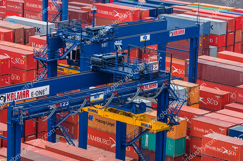
Automated tire-mounted cranes (hereinafter referred to as “tire cranes”. RTG are common lifting equipment in container terminal yards, primarily used for container stacking and loading/unloading.
They can move freely within the yard without relying on tracks, adapting to various complex terrains, and offer advantages such as high flexibility and convenient mobility. In practical applications, due to factors such as uneven ground, equipment wear, environmental interference, and operating errors, tire cranes often deviate during movement, causing the actual travel trajectory to deviate from the predetermined path.
The deviation of tire crane gantries may not only cause collisions between tire cranes and other equipment or containers in the yard, resulting in damage to equipment and cargo, but also increase the time required for correction and adjustment, resulting in a decrease in overall operational efficiency and an increase in terminal operation and maintenance costs. In view of this, how to optimize the tire crane gantry correction method and improve the safety and efficiency of automated operations has become a technical problem that needs to be urgently solved in ports.
Traditional Tire Crane Gantry Deviation Correction Methods
Magnetic Nail Deviation
The magnetic nail deviation correction method uses magnetic nails installed on the ground to position and correct the deviation of tire cranes. Specifically, magnetic nails are buried in the running path of the tire crane gantry, and a magnetic induction device detects the position of the magnetic nails to determine the deviation of the tire crane gantry and correct it.
The magnetic nail alignment method has significant limitations in practical applications, primarily manifested in the following aspects:
(1) Magnetic nails are prone to being crushed, requiring frequent maintenance and replacement, thereby increasing operational costs;
(2) The installation of magnetic nails involves substantial engineering work, with high requirements for ground construction, and is significantly affected by ground objects, thereby impacting detection accuracy.
Reflective strip deviation
The reflective strip deviation correction method uses visual capture equipment installed on the tire crane to capture the displacement of markers to determine whether the tire crane gantry is deviating.
The specific implementation steps are as follows:
(1) Draw standard lines on both sides of the tire crane gantry’s travel route and install reflective strips.
(2) The camera captures images of the reflective strips and uses image processing technology to identify the actual position and deviation of the tire crane gantry, thereby achieving correction. The advantage of the reflective strip deviation correction method is that it does not require contact with the ground, thereby reducing equipment wear and maintenance workload; the disadvantage is that it is susceptible to interference from light and weather conditions, especially in rainy or snowy weather or under low-light conditions, where the camera may struggle to capture high-resolution images, leading to reduced system stability and reliability.
Global positioning system positioning
The global positioning system (GPS) positioning correction method uses GPS signals for positioning and correction. It requires the construction of GPS reference stations and mobile stations in the stack yard, and the installation of differential receiving antennas on the tire cranes. By receiving and processing GPS signals, the position and offset of the tire crane gantry can be determined, thereby achieving correction. The advantages of the GPS positioning correction method include mature technology, a wide positioning range, and suitability for large-scale yards [4]. However, its disadvantages include potential issues such as reduced accuracy and signal delay in the short term, which may affect system stability and effectiveness. Additionally, the system relies on external devices (such as radio stations or local area networks), leading to increased system complexity and maintenance costs.

New Correction Solution For Tire Crane Gantries
Given that a single method is difficult to meet the all-weather correction needs of tire cranes in complex environments, this paper proposes a new correction solution that integrates the magnetic nail correction method and the reflective strip correction method. By combining the advantages of both, it is possible to flexibly switch between correction modes under different environmental conditions, thereby ensuring system stability and reliability and improving the efficiency and safety of tire crane automation operations.
Based on the current status of an automation project at a certain terminal in Xiamen Port, this solution integrates optical ranging, image processing, intelligent control, wireless radio frequency, and other technologies to design an automatic positioning and deviation correction control system for tire gantry cranes (see Figure 1). The specific implementation steps are as follows.
(1) Install a positioning and deviation correction board in the sliding contact line bracket next to the tire crane gantry runway beam, and install two intelligent vision sensors on both sides of the gantry.
The intelligent vision sensors detect the position information of the positioning and deviation correction board, convert it into an optical fiber signal and transmit it to the electrical room, where it is converted into an Ethernet signal and transmitted to the controller. The controller calculates the current gantry posture, including the gantry position and gantry torsion deviation, and uses intelligent control to set the speed of the front and rear gantry drivers to achieve real-time deviation correction of the gantry.
(2) Reuse the laser ranging system used on the original machine to detect the distance of the sliding contact line, detect the displacement of the gantry deviating from the sliding contact line in real time, and output the switch signal to the single machine electronic control system to control the gantry to slow down and stop.
(3) A magnetic nail positioning system for attitude correction is installed on the tire crane door leg, using a dual-axis absolute position measurement method based on wireless radio frequency technology to read the absolute position code of the magnetic nail installed on the ground and calculate the position of the magnetic nail under the antenna, thereby measuring the absolute position of the gantry.

(4) Combined with the original machine’s incremental encoder system, the single-machine control system calculates the current position of the gantry through logical operations and ensures the continuity of the position. Finally, the data is transmitted to the automatic control system to achieve automatic positioning and correction of the gantry.
The deviation correction process of the tire crane gantry automatic positioning and deviation correction control system based on the new integrated deviation correction solution is as follows: Under normal environmental conditions, the system prioritizes the use of reflective strip deviation correction and laser ranging systems, with intelligent vision sensors detecting the positioning deviation correction plate and the controller calculating the gantry position and attitude to achieve gantry trajectory control.
Under severe weather conditions (such as rain or snow), the intelligent visual sensor cannot work normally, so the system automatically switches to the magnetic nail deviation correction method, with the laser ranging system and positioning system detecting the position of the magnetic nails and calculating the displacement and attitude deviation of the gantry to ensure the accuracy and stability of the gantry trajectory.
It can be seen that the automatic positioning and correction control system for tire crane gantries based on the new integrated correction solution achieves seamless switching and data integration between the upper-level automatic control system and the single-machine basic electronic control system through data interaction: under normal conditions, the system uses high-precision data provided by intelligent vision sensors to achieve correction; in emergency situations, the system uses stable positioning data provided by magnetic nail sensors to achieve correction, ensuring reliable correction in all weather conditions.
Container Spreaders Designed For Tire-mounted Gantry Cranes
In the busy operations of container terminals, GBM brand container spreaders offer significant advantages to tire-mounted gantry crane (RTG) users with their outstanding performance.
GBM Design Lightweight steel structure
While ensuring extreme structural stability and excellent fatigue resistance, it significantly reduces the self-weight of the spreader. This not only alleviates the load burden on the RTG but also enhances the equipment’s maneuverability and response speed, making lifting operations more convenient and efficient while effectively reducing energy consumption.
Integrate Automatic Telescopic Systems
Whether it is the rapid automatic switching between containers of different sizes or the accurate and efficient lifting/lowering movements, the conversion and operation cycle time of lifting operations is greatly reduced, significantly improving the overall operational efficiency and terminal throughput capacity of RTGs.
Core Components From Global Brands
These rigorously validated components ensure precise and reliable power transmission, stable and sensitive signal control, greatly enhancing system durability and stability, effectively reducing downtime due to failures, and ensuring the crane can reliably serve in high-intensity terminal operating environments for the long term, maximizing return on investment.

Conclusion
This article analyzes the advantages and disadvantages of magnetic nail deviation correction, reflective strip deviation correction, and GPS positioning deviation correction methods for tire crane gantry deviation problems, and proposes a new deviation correction solution that integrates magnetic nail deviation correction and reflective strip deviation correction methods.
Test results demonstrate that the new integrated correction scheme effectively overcomes the limitations of single correction methods, providing stable and reliable positioning correction functionality under various environmental conditions, thereby significantly enhancing the safety and efficiency of tire crane automated operations.
For more details,please kindly contact us for free consultant:sales.export@gbm-china.com