

Similar to belt conveyors (hereinafter referred to as belt machines), plate conveyors (hereinafter referred to as plate machines, including scale plate conveyors, flat plate conveyors, etc.) also experience misalignment issues. Severe misalignment in plate conveyors not only increases operational resistance but can also accelerate wear on the entire traction chain, potentially rendering the machine unusable within a few years. This is a problem that must be addressed.
Causes of Plate Conveyor Misalignment
Plate conveyor misalignment can stem from various causes, such as: causing the conveyor to drift toward the adjusted direction, much like turning a car’s steering wheel. Alternatively, if the symmetrical centerlines of the head pulley’s two sprockets do not align with the conveyor’s longitudinal centerline, the conveyor will drift toward the misaligned side. Furthermore, if the head pulley’s main shaft is not installed level, gravitational force will cause the conveyor to drift toward the lower end.
These issues stem from installation deviations. The principle is straightforward and intuitive, and solutions are readily available. Adhering to industry standards during installation prevents deviation problems.
Practice has proven that the primary cause of plate conveyor deviation is asynchrony between the two sprockets on the head drive shaft.
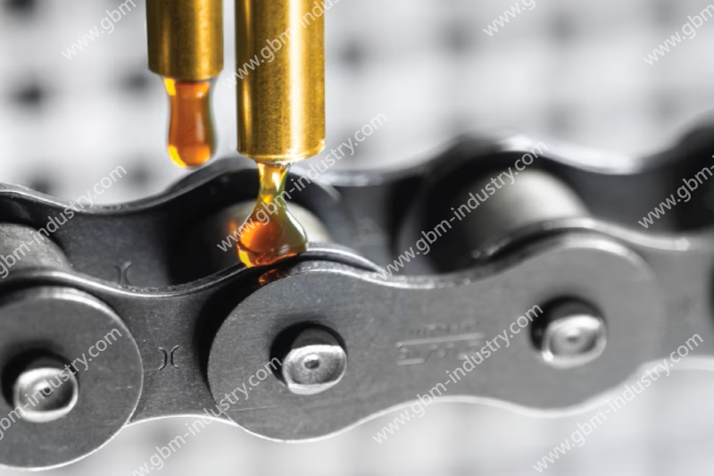
First, let’s introduce the structural characteristics of plate conveyors. Similar to belt conveyors, plate conveyors operate with a belt or plate belt driven by the head pulley and tensioned by the tail pulley, circulating continuously. Supported by frames, idlers, or rollers, they carry material on the upper section and return empty on the lower section. What distinguishes the plate conveyor from the belt conveyor is its load-bearing structure. The plate conveyor uses steel plates or other robust materials that are impact-resistant and high-temperature resistant, making it irreplaceable by belt conveyors. The load-bearing structure of the plate conveyor is formed by plate chains linked together, also a flexible structure. However, the flexibility of the plate conveyor is stepped, meaning each section connects to the next. Its pitch is the same as that of the drive chain. In contrast, the belt conveyor has no pitch and is stepless.
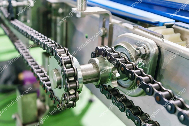
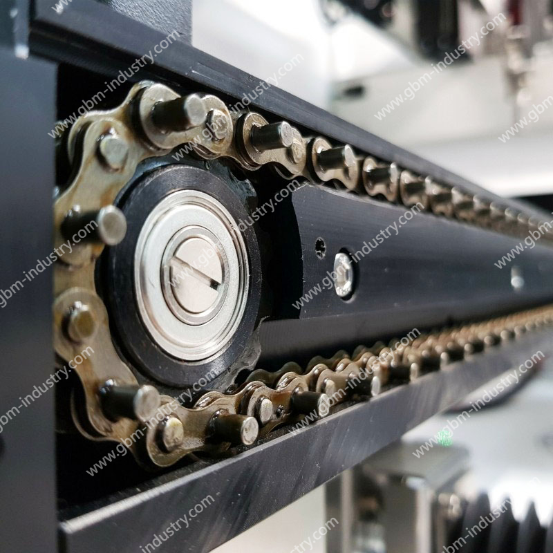
Since plate conveyors employ chain drive, the head pulley’s main drive shaft assumes a commanding role. This master shaft drives the entire plate belt system via two sprockets mounted on it. Typically positioned on either side of the plate belt, these sprockets are spaced wider than the belt’s width. If the two sprockets lose synchronization, the leading sprocket pulls the plate belt toward its side, causing lateral deviation. This principle mirrors flat belt drives, where the drive pulley is often designed as a drum. The drum’s center has the largest diameter, guiding the flat belt toward the center to maintain proper transmission. This is the common concept of “tight belt” and the rationale for drum-shaped pulleys.
So, what causes the two sprockets to become out of sync? Below are two aspects of analysis.
(1) Manufacturing-induced asynchrony is a common cause.
To achieve synchronization, design drawings specify clear technical requirements: the keyways for mounting both sprockets on the shaft must lie on the same generatrix and be symmetrical relative to the shaft centerline. While milling keyways on a boring machine is generally straightforward, fitting errors can still occur. Construction drawings for the two sprockets also emphasize that the position of the teeth relative to the keyways must be consistent. In some cases, it is even required that both sprockets be mounted on a single keyed shaft and machined together to ensure uniformity. These machining requirements pose significant challenges. As large components, the sprockets have hub lengths exceeding 120mm. Despite having only 6 to 8 teeth, their large pitch typically results in a pitch diameter greater than 500mm. Stringing together two such large components for simultaneous gear tooth machining is practically difficult. The current common approach involves separate machining using template marking. When keyways are machined using this method, if one is offset 0.25 mm to the left and another 0.25 mm to the right, the combined offset becomes 0.5 mm. This offset is magnified 4 to 5 times when projected onto the sprocket pitch diameter, resulting in a 2 to 3 mm misalignment. This is sufficient to cause the trigger mechanism to run off-center. While this example may be somewhat exaggerated, a misalignment of 1–2 mm is common.
Such misalignment caused by asynchronous advance is not severe enough to render the conveyor inoperable in the short term, which is why it often goes unnoticed. However, the consequences of long-term operation are evident: increased running resistance and gradual wear of the flange on one side of the conveyor’s rollers.
(2) Insufficient spindle rigidity causing asynchronism is a latent cause often overlooked.
Yet it may be the primary reason for scrapping the entire machine. When conveying distances are short, loads are light, and traction forces are low, spindle rigidity calculations are generally unnecessary. However, under heavy loads and high traction forces, spindle torsional rigidity verification becomes mandatory.
It should be noted that plate conveyors in the foundry machinery industry operate under low-speed, high-torque transmission conditions, typically with spindle speeds of 1–2 r/min. Although power consumption is only a few kilowatts, the torque.
Under immense torque, the sprocket on the non-drive side experiences tooth lag due to shaft torsion. If the shaft twists by 0.05 degrees across the distance between the two sprockets—assuming a 1,500 mm spacing— the displacement at the keyway would be 1.3 mm. This displacement would translate to 6 mm on the pitch circle diameter, causing the chain to severely drift toward the drive side. This demonstrates that the main shaft must possess sufficient rigidity, with virtually no torsional deformation permitted.
Prevention and Control of Misalignment
(1) Manufacturing Processes Ensure synchronous tooth formation on both sprockets, with the keyways on the main shaft lying on the same cylindrical generatrix. Currently, main sprockets are typically fabricated by CNC flame-cutting teeth from steel plates, welding the hub, and then machining the keyway after finishing the bore. Carefully marking the keyway position lines using templates generally ensures precision.
(2) Place the assembled spindle assembly on a platform for inspection. Grind away the protruding teeth in the direction of rotation.
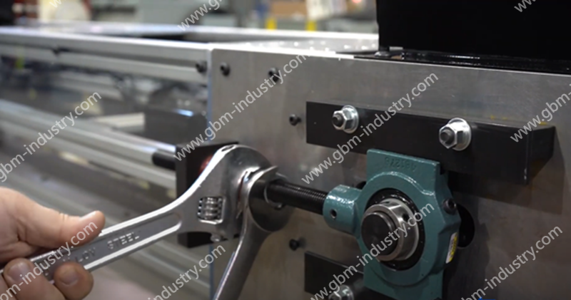
(3) Weld stop plates on both sides of the two bearing housings mounted on the headstock to securely fix them in place. This method, adapted from a Japanese company’s practice, prevents bearing housing bolts from shear stress and is simpler and more reliable than using locating pins. Apply this same approach to the tailstock tensioning seat by welding stop plates for fixation.
(4) During final assembly, adhere to industry installation standards. Ensure the spindle axis is perpendicular to the longitudinal centerline of the scale plate, and its symmetrical centerline aligns with the conveyor’s longitudinal centerline.
(5) If a running scale plate conveyor deviates, systematically analyze causes per the above discussion. After debugging, weld stop plates for fixation. If misalignment is minor, gravity-based correction may be applied: appropriately raise the bearing housing on the deviated side. Gravity will then shift the conveyor toward the opposite side. Practice demonstrates this method is simple and effective, as the main shaft typically uses self-aligning bearings, allowing a few degrees of offset without hindering operation.
GBM Professional Belt Conveyors: Preventing Misalignment at the Source
As a specialized manufacturer of bulk material handling equipment, GBM deeply understands the structural characteristics and operational mechanisms of belt conveyors. We rigorously control every critical step in the production process to prevent misalignment at its source, delivering highly efficient and durable professional belt conveyors to our customers.
In the core process of sprocket manufacturing, GBM strictly adheres to the “dual sprocket synchronization” technical standard. Addressing the common issue of “keyway position deviation causing sprocket desynchronization” mentioned in the article, GBM employs CNC machining centers to mill both keyways on the main shaft in a single setup. This ensures both keyways lie on the same cylindrical generatrix and are absolutely symmetrical to the shaft centerline. For the sprockets themselves, GBM abandons traditional template-marking and separate machining methods. Instead, it employs high-precision CNC gas cutting and specialized fixture positioning to guarantee consistent height alignment between each sprocket tooth and its keyway during tooth profile machining. Through this “dual precision assurance for both shaft and sprocket,” GBM controls circumferential displacement between the two sprockets within an extremely narrow range, eliminating potential misalignment risks caused by manufacturing errors at the production stage.
The overall structural design of GBM belt conveyors fully considers material characteristics and on-site conditions. For transporting high-temperature, high-abrasion materials like cement clinker, GBM employs high-strength scaled plates and wear-resistant rollers. Combined with self-aligning support roller assemblies, these components automatically compensate for lateral forces caused by uneven loading, maintaining stable belt operation. Prior to shipment, GBM undergoes simulated load testing to verify head/tail pulley parallelism, sprocket synchronization, and overall straightness, ensuring rapid stabilization upon on-site installation.
Choosing GBM’s professional belt conveyors means comprehensive quality assurance throughout the entire process—from design and manufacturing to installation. Whether for new projects or retrofitting existing equipment, GBM provides customized solutions for misalignment issues, significantly reducing maintenance costs, extending the service life of the entire machine, and creating greater production benefits for customers in the cement, mining, foundry, and other industries.