

Introduction
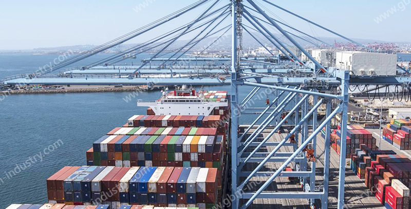
Container crane hook engagement (hereinafter referred to as hook engagement) collectively refers to situations during container handling operations where, due to various reasons, the crane hook becomes hooked or interferes with fixed structures (such as container guide rails in the ship’s hold or containers fixed to the ship) during the lifting process, resulting in severe instantaneous overload of the lifting load and imposing massive overload impact on the lifting mechanism and STS crane structure. When hooking occurs, it can be broadly categorized into four types based on the hook’s load status: 1. Empty hook assembly interference or snagging with container guide rails during lifting operations within the ship’s hold; During lifting, containers suspended beneath the spreader interfere with or become jammed in the ship’s guide rails; Lifting occurs while containers suspended beneath the spreader remain connected to adjacent containers, causing a snag; A snag caused by both the spreader and the containers it carries.
Analysis of Causes For STS Crane Lifting Gear Hanging
The occurrence of hook-up incidents is the result of the combined effects of equipment itself, operational environment, and human factors. From the perspective of equipment safety, especially as terminal operations become increasingly automated, human factors are mitigated. It is therefore necessary to strengthen analysis of hook-up causes stemming from the equipment itself under continuous operational conditions.
Hook-up incidents primarily result from the following six categories:
Luffing Caused by Container Spreader Issues
During actual operations, this occurs when The spreader itself is deformed or aged, or its guide plates are warped, causing the four corners of the container or corresponding mechanisms to exceed the original design envelope dimensions; The effectiveness of the spreader’s four-corner guidance devices is insufficient; The spreader’s telescopic beams are inaccurately positioned or malfunction and move unexpectedly.
Container Deformation Causing Liner Hang-ups
When deformed containers are lifted and moved within the container ship’s guide channels (including both interior and deck sections) by lifting gear, the portions exceeding the container’s original design envelope dimensions may interfere with or become snagged on the ship’s guide channels or adjacent equipment, increasing the likelihood of lifting gear snagging.
Container Gantry Hooking Caused by Deformed Shipway Guides
Deformed cargo hold guideways disrupt the intended travel path for containers or spreaders. Even when spreaders or containers meet ideal standard dimensions, the intrusion of deformed guideways into the original travel path inevitably causes interference or snagging between the deformed guideways and the spreader or container. This correspondingly increases the probability of spreader snagging.
Container Ship Listing and Luffing Causing Luffing Device Snagging
The vessel’s swaying inclination and lateral displacement relative to the STS crane’s travel direction can accumulate to the point where they intersect with the lifting trajectory of the spreader (or the container suspended beneath it). This causes interference or even jamming of the spreader (or the suspended container) during the lifting process. Conversely, even with properly secured ship mooring lines, the tilt of the lifting device (or the container suspended beneath it) can cause its lifting trajectory to intersect with the predetermined permissible trajectory within the ship’s hold. This can result in similar issues to those caused by ship sway, such as the lifting device becoming snagged on the hold. Additionally, improper tilt angles of the crane’s lifting device itself or uneven cargo distribution within the container suspended by the device can cause the lifting device (or the container suspended below it) to tilt.
When a container awaiting lifting is manually secured to any shipboard fixture, initiating the lifting operation before releasing this connection can also cause the lifting device to hang on the hold.
Hook Catch Caused by Operator Error
Under identical conditions for a specific operation, different crane operators and auxiliary personnel will exhibit varying operational responses. These differing responses inevitably produce different operational outcomes.
Safety Protection Measures to Mitigate Impact
More mature hanger protection program
According to the current realization of cabin protection, the corresponding device can be roughly divided into five sub-modules.
The combination of the above modules, through the actual promotion and application, formed the following more mature application program.
3.1.1 Load Sensor + Dedicated Hook-Up Detection & Signal Generation Module + Electrically Controlled Safety PLC/Drive Emergency Stop Base Control
(1) The load sensor employs a pin-type design. The PLC analyzes load trend data from the sensor to enable preemptive hook-up protection. Combined with the dedicated hook-up detection and signal generation module, it rapidly and accurately generates hook-up protection signals.
(2) Three load-hanging protection signals participate in the protection mechanism: – One signal is bus-transmitted to the PLC for logic control, engaging the working and emergency brakes. – One signal directly connects to the inverter control board, halting motor current input at the IGBT level. The remaining two signals are transmitted to the safety-level I/O module, where they trigger the inverter’s safe torque off function via the safety-level industrial bus.
3.1.2 Cabin-Hooking Protection Cylinder Pressure Relay (or Pressure Sensor) + Electrically Controlled Safety PLC/Low-Level Drive Emergency Stop Control + Passive Compression Unloading of Cabin-Hooking Protection Cylinder
(1) Utilizing a mechanical contact-type cabin suspension protection cylinder pressure relay or pressure sensor, the cabin suspension protection signal is generated and output by detecting the pressure in the cabin suspension protection cylinder. If a mechanical pressure relay is used in this scheme, the response time of the cabin suspension protection signal is relatively prolonged.
(2) The cabin protection signal is similarly divided into three paths for cabin protection: one path is input via the bus to the PLC for logic control, engaging the working brake and emergency brake; one path is directly connected to the inverter control board to halt current input to the motor at the IGBT layer; the remaining two signal paths are transmitted to the safety-rated I/O module, where the inverter’s safe torque off is achieved through safety-rated industrial bus control.
(3) The cabin suspension protection cylinder operates via its own hydraulic system. When internal pressure reaches the set action value, the cylinder unloads and compresses, reducing the load on the hoisting wire rope.
Your Professional STS Parts Partner
Comprehensive Range, One-Stop Procurement
GBM’s extensive product database and robust supply chain system deliver a one-stop sts spare parts procurement solution, significantly reducing the time and communication costs associated with sourcing and coordinating multiple suppliers.
Superior Quality, Reliable Performance
Quality is our non-negotiable baseline. All GBM products are manufactured using premium materials, advanced production techniques, and stringent quality control systems (compliant with ISO 9001 and other international standards). Each item undergoes rigorous testing to ensure its wear resistance, fatigue strength, and overall performance meet or exceed OEM standards, providing robust assurance for your equipment’s safe and efficient operation.
Rapid Delivery and Responsive Service
We fully understand the significant losses downtime inflicts on ports. GBM has optimized its global supply chain layout and established strategic inventory bases, drastically reducing spare parts delivery cycles. Regardless of your location, we respond swiftly with efficient logistics solutions to ensure urgently needed parts reach your site immediately. This enables rapid production resumption and minimizes downtime impacts.
Conclusion
Through scientific analysis of the causes behind container crane hooking incidents, we gain clarity on the root causes of STS crane hooking problems. This enables the development of scientifically sound and effective preventive and remedial measures. By prioritizing STS crane hooking protection, we significantly reduce the likelihood of hooking incidents. Even when unavoidable hooking incidents occur, the process can be promptly interrupted to maintain control, thereby safeguarding both operators and the entire STS crane during operations.