

As critical handling equipment at port terminals, grab unloaders perform the vital task of discharging bulk cargo from ships. Their operational status directly impacts port handling efficiency and economic performance. Bridge grab unloaders have become the most widely used type of unloader due to their simple structure, high reliability, and efficiency. However, operating in harsh environments with high intensity and complex structures, equipment failures occasionally occur. Once a failure happens, it not only interrupts loading/unloading operations, affecting vessel turnaround and port production schedules, but may also trigger safety incidents, resulting in casualties and property damage.
 Overview of Bridge Grab Unloaders
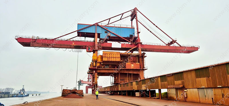
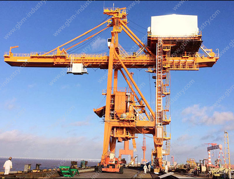
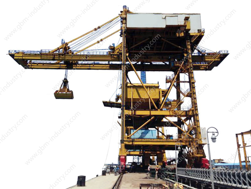
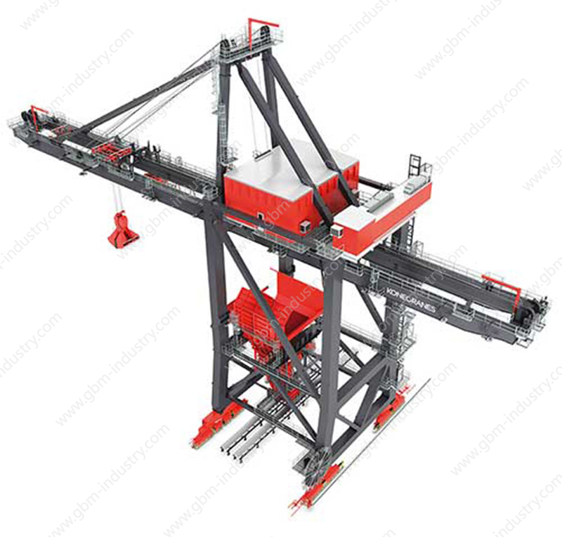
Bridge grab unloaders primarily consist of a bridge frame, grab, hoisting mechanism, opening/closing mechanism, trolley travel mechanism, crane travel mechanism, and electrical control system. The bridge frame serves as the unloader’s supporting structure, typically constructed from steel to ensure sufficient strength and rigidity. The grab is the core component, designed to grasp and unload cargo. Depending on the material handled, grabs are categorized as light-duty, medium-duty, or heavy-duty. The hoisting mechanism and opening/closing mechanism control the grab’s vertical movement and opening/closing actions. The trolley travel mechanism and crane travel mechanism enable horizontal and vertical movement of the grab, while the electrical control system manages and monitors the entire equipment’s operation.
During operation, the main crane travels along the quay rails to position above the vessel. The trolley mechanism then moves the grab to the designated location within the ship’s hold. The hoisting and opening/closing mechanisms coordinate to lower the grab, grasp the cargo, lift it, and close the grab, raising the cargo to a specified height. Subsequently, the trolley mechanism moves the grab to the hopper above the quay. The hoisting and opening mechanisms operate again to open the grab, unloading the cargo into the hopper. The material is then conveyed via the feeding system beneath the hopper onto the belt conveyor for final transport to the stockyard.
Trolley or gantry derailment is the most common failure type, while cracks and deformation in metal structures require the longest repair time. These structural issues critically impact overall equipment safety and significantly disrupt production rhythms, making root cause analysis essential.
Analysis and Handling of Common Failures
Wire Rope Failures
Wire rope failures primarily involve breakage and loosening.
Wire rope breakage is mainly caused by strength reduction due to wear and corrosion, as well as permanent deformation resulting from overload. As the flexible component bearing the weight of the grab and ore, the wire rope endures complex stresses during each unloading cycle. Frequent contact, friction, and compression with pulley blocks and drums cause surface abrasion. Although the grab unloader employs a spray system for dust suppression, airborne particulates remain unavoidable, further accelerating surface wear. Structurally, wire ropes consist of multiple strands of fine steel wires twisted together. During loading, relative slippage occurs between strands and wires, causing internal wear. After prolonged use, some unloader ropes experience reduced load-bearing capacity due to excessive wear, eventually leading to failure from abrasion.
Furthermore, since unloaders are frequently used for handling ore at seaports, the highly saline and humid environment strongly corrodes the wire rope. If maintenance is neglected, leading to insufficient protective oil film on the rope, corrosion accelerates, ultimately causing unexpected breakage. Permanent deformation of wire ropes occurs not only in grab unloaders but also in other port machinery handling cargo. The primary cause is misalignment of the wire rope, leading to abnormal contact with pulley blocks or drums. This results in localized excessive compression, causing permanent deformation.
The primary causes of wire rope loosening are the failure of C-type quick-release shackles and pear-shaped heads used to secure the rope ends. These failures result from both improper operation causing friction between the wire rope and hatch covers, as well as inherent quality defects in the C-type shackles and pear-shaped heads themselves.
In summary, the main causes of wire rope breakage and loosening lie in inadequate routine maintenance and improper operation. Therefore, during routine operation, it is essential to strengthen periodic maintenance and inspection of wire ropes, promptly analyze the causes of damage, and implement preventive measures. Particularly for ship unloaders at seaports, regular checks of the oil film thickness on wire ropes are required to ensure sufficient lubrication on the surface, preventing corrosion from high humidity and salt spray. Simultaneously, operator procedures must be standardized to prevent shock loads on the wire rope during unloading operations, as well as sudden impacts or friction with other structures. Such incidents can cause permanent deformation, reducing the wire rope’s strength.
Boom Retraction Malfunctions
When vessels berth at the wharf, the main beam of the bridge grab unloader must retract. During this process, jamming or incomplete retraction frequently occurs, most commonly at the 1/4 to 1/3 lift position. The primary cause is improper anchoring of the main trolley or rope support trolley, or deformation of the anchor seat. This prevents the control system from accurately determining the position of the main trolley or rope support trolley, thereby failing to execute the front beam lifting action. Improper anchoring of the main trolley or rope support trolley is mainly due to operator error or changes in the length of the traction wire rope, making it impossible to move the trolley to the correct position according to the preset control program.To address these faults: First, increase the adjustable range for anchoring the rope support trolley, thereby reducing the required anchoring precision. Second, operators must correctly execute the front beam retraction action. During retraction, utilize pre-tensioning methods to guide the rope support trolley’s wire rope, minimizing or eliminating impact forces from sudden traction. This prevents permanent deformation of the wire rope, reduces the frequency of length adjustments, and extends the wire rope’s service life.
Trolley or Gantry Rail Biting
Rail biting by the gantry or gantry is one of the most common phenomena during ship unloader operation. It occurs when the flange of the car or gantry continuously contacts the rail flange face due to factors like uneven loading, leading to progressive wear or even deformation of both the flange and rail. Over time, this phenomenon progressively worsens. Multiple causes exist: uneven wheel loading from off-center loads generates lateral forces during travel; poor track straightness resulting in excessively wide or narrow gauge spacing; and when gauge spacing is too wide, wheel deflection causes diagonal wheels to bite the rail.
When wheels operate under prolonged rail-biting conditions, distinct bite marks or friction traces become visible on the rails. This intensifies vibration in the travel mechanism and, in severe cases, may induce resonance in the steel structure, posing a safety threat to the ship unloader. Therefore, regular inspections of the wheels and rails on both the main and auxiliary travel mechanisms are essential to detect rail-biting. If detected, necessary measures must be taken based on the specific cause. For instance, if wheel misalignment causes rail biting, adjust the wheel installation tolerance by correcting wheel position and diagonal alignment. If drive mechanism asynchrony leads to travel mechanism skew, test and adjust the control system to synchronize drives while inspecting motors and transmission components for abnormal parts, while performing timely maintenance on the transmission mechanism. If rail straightness issues cause rail gnawing, promptly correct the rails. If lateral forces during operation result from uneven loading, consider eliminating the uneven load factors; if elimination is impossible, install leveling wheels on the travel mechanism.
Hopper System Failures
Common hopper system failures primarily stem from operator non-compliance or operational errors, causing components like receiving plates to sustain damage from ore impact. Sometimes, operators prematurely discharge material to increase unloading efficiency, causing ore impacts on the hopper that deform components. During routine operations, operators should be reminded to follow standard procedures, or control systems should be configured with restrictions to prevent unloading machines from executing non-standard actions. These issues have largely disappeared in automated unloading machines. Clearly, operator non-compliance is the primary cause of hopper system component damage.
Another common malfunction in the hopper system is material blockage. This primarily occurs when the designed ore type significantly differs from the actual incoming material, causing the hopper shape and vibrating feeder to fail in effectively guiding the ore flow. Traditional bulk material handling equipment designs often assume ore behaves like a fluid, which deviates significantly from reality. Consequently, older bridge grab unloaders frequently experience hopper blockages. Currently, many companies have adopted DEM (Discrete Element Method) simulation technology to guide unloading system design. By fully considering the flow characteristics of various ores during the design phase, newly designed hopper systems experience significantly reduced material blockages.
GBM Provides Professional Grabs for Ship Unloaders
Given the susceptibility of bridge grab unloaders to failures under complex operating conditions, selecting high-quality, highly adaptable grapples is crucial for enhancing equipment stability and operational efficiency. As a specialized grab manufacturer deeply rooted in bulk handling equipment, GBM is dedicated to providing ports and terminals with high-performance, structurally reliable grab solutions. GBM grabs utilize high-strength wear-resistant steel combined with advanced structural design and manufacturing processes, effectively withstanding high-intensity, high-frequency operational environments. This significantly reduces risks of abnormal wire rope stress and structural deformation caused by fatigue and wear in the grab body.
GBM offers customized grab solutions tailored to material characteristics, ship unloader models, and operational conditions. This ensures seamless integration with unloader systems, enhancing overall operational fluidity and safety. Choosing GBM grabs not only minimizes equipment downtime and extends service life but also delivers more efficient and stable unloading operations for ports. This supports cost reduction, productivity gains, and safe production objectives.