

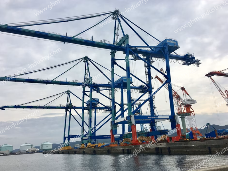
The operational efficiency of a container STS crane is largely determined by the performance of each of its components. Key mechanisms include the gantry mechanism, the trolley mechanism, and the hoisting mechanism. As a vital component, the trolley mechanism primarily supports the wire rope to prevent excessive sway during lifting operations. In actual production, frequent failures of the bracket trolley often compromise the overall efficiency and reliability of the crane.
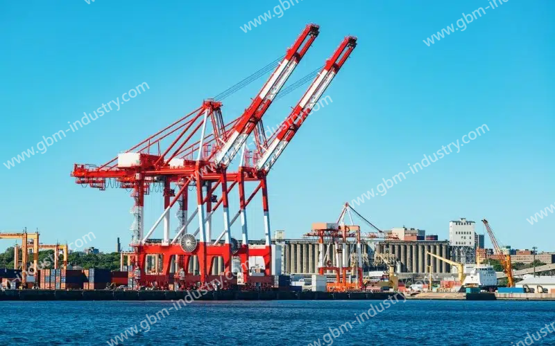
Overview of STS Crane
In recent years, with continuous advancements in China’s machining capabilities and control technologies, shore container trolley cranes are evolving toward larger sizes, greater intelligence, and full automation. Primarily deployed in coastal environments, these cranes operate under harsh conditions. The trolley mechanism performs lifting functions within the crane, yet its complex internal components are prone to failures that disrupt crane operations. This paper focuses on the rope winding mechanism of the gantry trolley in shore container cranes. Based on an analysis of its current state, corresponding optimization measures are proposed.
Analysis of Gantry Trolley Winding Mechanism
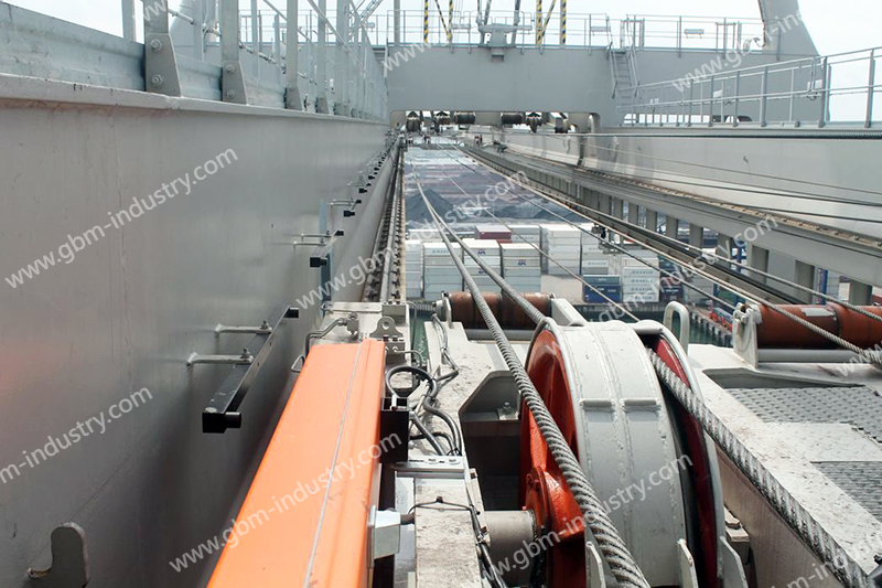
Currently, the rope winding mechanisms of crane gantry trolleys all employ a dual-rope synchronous traction method for lifting wire ropes. This dual-rope trailing method ensures a longer service life for the wire ropes, typically exceeding two years. However, this type of trolley winding mechanism exhibits a relatively high failure rate, manifested in the following aspects.
(1) Currently, the wire ropes used in this type of container crane have a diameter of 12.5mm and consist of eight rope ends, each secured via rope tie posts. These tie-off posts are located on the trolley and the bracket of the trolley’s traction mechanism. This means all tie-off posts are suspended, making subsequent wire rope replacement difficult. Rope replacement personnel cannot find a suitable standing position, often forcing them to walk on the trolley to complete the operation, posing significant safety hazards.
(2)The trailing rope position on this type of shore container crane is secured solely by rope clamps on the outer side of the crossbeam. Firstly, this design forces operators to position their upper bodies outside the bracket trolley mechanism during rope replacement, creating significant safety hazards. Secondly, even after the rope clamps release the wire rope during replacement, operators must still manually pull the wire rope, a process that is extremely strenuous. Finally, when re-clamping the wire rope after replacement, operators must simultaneously pull the rope and secure the clamping plate. This often causes the wire rope to be pulled diagonally outside the clamping plate’s groove. Operators then need to hammer the outer section of the wire rope back into the groove, a method that reduces the wire rope’s service life.
(3) After wire rope replacement by the current bracket trolley’s winding mechanism, the trolley’s position deviates from its pre-replacement location. Consequently, the trolley must be repeatedly repositioned to its intended location post-operation. This process is both time-consuming and labor-intensive.
(4) The current bracket trolley’s winding mechanism requires reserving 20 meters of slack during wire rope winding for subsequent guiding and pulling operations, resulting in wire rope wastage.
In summary, the current wire rope winding mechanism of the bracket trolley poses significant safety hazards to operators during wire rope replacement. The replacement process is both time-consuming and labor-intensive, leading to prolonged crane downtime and substantially reducing loading/unloading efficiency. Evidently, the current crane bracket trolley winding mechanism presents substantial difficulties for rope replacement, jeopardizes the safety of personnel performing the task, and restricts crane loading/unloading efficiency.
Design of the Winding Mechanism Optimization Solution
Based on the analysis of the aforementioned issues with the winding mechanism and drawing upon years of practical experience, the winding mechanism is optimized through the following design approaches.
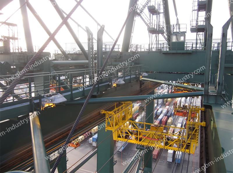
(1) Addressing the complexity of the current design with eight rope heads and the issue of suspended mooring posts, the following improvements were implemented: – Installing a redirecting fixed pulley at the original mooring post location to redirect the wire rope toward the cantilever connecting beam and seaward bracket trolley. A pair of balancing pulleys is added at the original mooring post location to simplify the wire rope end securing process. To prevent lateral movement between the left and right wires within the balancing pulleys, a horizontal wire clamping plate is installed at the midpoint. This plate adjusts the lateral position of the wires, thereby controlling the balancing state of the bracket trolley.
(2) Remove the rope clamping plates from the outer side of the crossbeam and install a fixed pulley at their original mounting positions. This fixed pulley primarily redirects the wire rope onto the bracket trolley. Install a guide groove at the crossbeam’s corner to ensure smooth transition of the wire rope. Additionally, a specialized rope-pressing plate is added beside the guide groove. These modifications—removing the original rope-pressing plate, installing the redirecting fixed pulley, adding the guide groove, and placing the rope-pressing plate near the groove—significantly resolve the difficulties and safety hazards associated with wire rope replacement. They also prevent dragging the wire rope. Following this optimized design, the wire rope no longer exhibits misalignment. Consequently, hammering to realign it is unnecessary, eliminating the risk of compromising its strength and service life through hammer impact.
(3) Optimizing the original 4-rope inner/outer configuration to a 2-rope inner/outer arrangement reduces wire rope dragging difficulty. This significantly shortens the auxiliary wire rope length required for dragging, saving approximately 15 meters.
Application Effectiveness of Optimized Winding Mechanism
Based on the described optimization approach, corresponding components must be installed on the shore-based container crane bracket trolley mechanism. These include: 4 sets of #1 fixed pulleys, 4 sets of #2 fixed pulleys, 2 sets of #1 balancing pulleys, 2 sets of #2 balancing pulleys, 2 sets of #1 rope pressure plates, 4 sets of #2 rope pressure plates, and 4 guide channels. The winding mechanism of the shore container crane’s bracket trolley was modified using these components. The application results of the modification can be summarized as follows:
(1) After modification, wire rope replacement operations and processes were simplified while ensuring the safety of personnel involved in rope change tasks;
(2) The time required for rope replacement by the modified winding mechanism is only 4 hours, a significant improvement compared to the 15 hours needed before modification, greatly enhancing crane utilization;
(3) Compared to the pre-modification setup, the modified winding mechanism saves approximately 80 meters of auxiliary wire rope during rope replacement, reducing replacement costs;
(4) The modified winding mechanism facilitates easier adjustment of the bracket trolley’s lateral balance, thereby reducing subsequent maintenance and adjustment time and costs for the trolley.
Be Your Professional Supplier Of Port Cranes Operation
On the bustling stage of container handling, the STS crane stands as the undisputed “giant,” whose efficient and stable operation directly impacts the lifeline of port throughput. GBM fully understands this critical responsibility. We specialize in providing this “giant” with a full range of high-performance professional spare parts, covering core components such as brackets, high-strength wire ropes, and precision sheaves.
GBM selects premium materials and adheres to precision manufacturing processes, ensuring every spare part delivers exceptional durability and reliability. This significantly safeguards the stable and long-term operation of STS crane equipment while effectively reducing the risk of unexpected downtime.
Choosing GBM means choosing worry-free assurance. We deliver not just products, but comprehensive technical support and after-sales service spanning the entire equipment lifecycle. From precise selection guidance to efficient replacement support—especially for specialized tasks like bracket adjustments and wire rope winding—our team provides solid backing, ensuring your equipment remains in optimal, efficient, and safe operating condition.
Conclusion
As one of the primary devices for transferring cargo container from ships to the dock front, the reliability and stability of a quay container crane directly determine its utilization rate and cargo handling efficiency. To ensure high reliability and safety, stringent requirements are placed on the reliability and rationality of every component and subsystem. The original bracket trolley rope winding mechanism faced practical challenges including complex wire rope replacement procedures, significant safety hazards, and time-consuming maintenance. Therefore, drawing on years of operational experience, we optimized the design by incorporating fixed pulleys, balancing pulleys, specially designed rope pressure plates, and guide channels.